The controlled nuclear synthesis
The first page of the description of the invention. (Below I gives
translation into the English language of the first and final phrases)
(For increase of the image you click on him the left button of the mouse)
The description of a mode of the decision of problem CNS:
(the article is written on the basis of four applications on the invention)
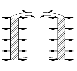
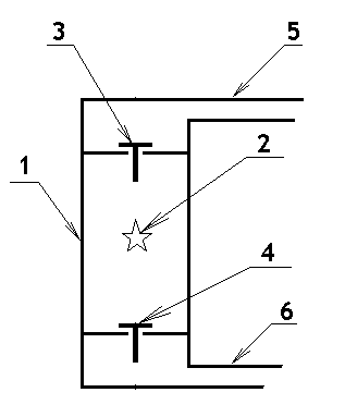
Drawing 2.
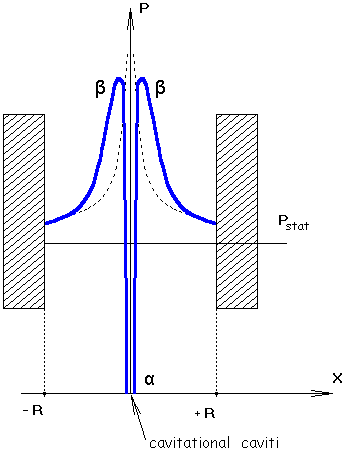
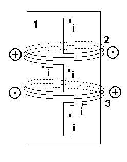
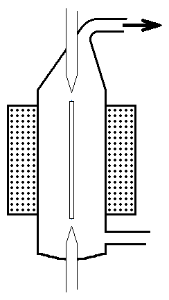
The image 2 show a cylindrical oscillator in a vertical section. A image 3 - the view from above. On all images, submitted here, thick arrows designate a directions of radial fluctuations of walls of a cylindrical oscillator. In other words, authors of the listed patents, were going to receive a concentration of energy of sound fluctuations in the geometrical centres of symmetry of oscillators.
Theoretically in similar oscillators the increase of amplitude of pressure of a sound wave would be in inverse proportion to distance from the geometrical centre of symmetry of a oscillator or to a square of distance, for a spherical oscillator:
P ≈ 1/x or P ≈ 1/x2, (1)
Thus, as it was earlier specified, calculation of sizes of pressure and temperatures on the final stage of collapse of the absolute empty cavitational cavities in itself already gives infinite large values. And if besides it the collapse of this absolute empty cavitational cavities we make with help of the focused sound waves, then the value of sizes t and p on the final stage of process will have calculating values, proportional ∞2 (or ∞3 for a spherical oscillator). Therefore there is a probability, that at the appropriate sizes of oscillators in their geometrical centres it will be possible to receive conditions, sufficient for implementation of reactions of nuclear synthesis, even despite of presence of gases in cavitational cavities.
In principle, it is correct reasonings.
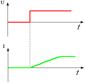
However the mistake of researchers in this, what at use for excitation of radial fluctuations of walls of oscillators of sine wave or any other electric signal, which have half-periods with equal to duration and with equal absolute amplitudes, be impossibly receiving significant amplification of the phenomenon of sonoluminescence in the geometrical centers of symmetry.
In particular, the similar mistake has been admitted by authors of the sensational work of group of Taleyarkhan's etc. These researchers for producing and collapse of the cavitational bubbles in the geometrical center of symmetry of a cylindrical oscillator used sine wave sound waves (harmonic waves) with frequency 19,3 kHz. As a result authors of the specified work did the foam from the set cavitational bubbles near to the geometrical center of symmetry of a cylindrical oscillator. But foam, as everybody knows, is the good acoustic insulation material, because of it the group of Taleyarkhan's not can concentrate the energy, which sufficient for excitation of the cavitational nuclear synthesis directly in the geometrical center of symmetry of a cylindrical oscillator - the foam shielded passage of a sound. Therefore, not looking at
enough thorough mathematical calculations, which, how it should seem, testify to an opportunity sonofusion at a collapse of the gas bubble, the group of Taleyarkhan's in practice did not manage
to receive indisputable experimental proofs of existence of nuclear reactions in the cavitational processes. And the reason of misfortune of researchers from this international group is in use of harmonious sound waves. (Here you can see this work and my comments).
(The note: in 2006 the researchers E.A.Smorodov and R.N.Galiakhmetov come to a similar conclusion about impossibility to use sine sound waves for amplification of the cavitation processes.
Look their article: " Calculation of installation for cumulation of energy in gas bubbles ", which was duplicated from the INTERNET.)
Really, if we carefully investigate this question, then we come to a unequivocal conclusion what to receive of the stationary wave, caused by a sine wave signal, in cylindrical or spherical oscillators impossibly, if in the geometrical centre of symmetry of a oscillator there is a process of liberation of energy.
For understanding, why in spherical or cylindrical oscillators impossibly effectively using of the standing waves, caused by a sine wave signal, for excitation of processes sonoluminescence and to receive due to it reactions of nuclear synthesis, we use receptions widely distributed in mathematics "reasoning from contrary" and "reduction ad absurdum". Let's make an assumption, which afterward in process of the logic analysis lead us to the contradiction with this, made earlier, an assumption
We now mentally shall present (we shall make an assumption, which contradicting to the experimental facts), that at use of standing sound waves in the centres of symmetry of cylindrical or spherical oscillators is observed very powerful liberation of energy - there occur the nuclear microexplosions
Now it will be pertinent to remind, what represents from itself the standing wave in strict mathematical sense. Look through the book: B.M. Javorsky, J.A. Seleznev "The reference book on a physics" (for those, who, matriculate and for self-education). Publishing house: "Science". The main edition of the physical and mathematical literature, 1984; with changes in 1989. Page 328:
"The special case of interference of waves is the standing waves. The standing wave in the general case is formed as a result of imposing two waves extending in mutual opposite directions, if the interfering waves satisfy to the following conditions: their frequencies, amplitude and a direction of fluctuations should be identical."
In this a definition I have specially emphasized words: frequencies and amplitudes should be identical.
In a case with focusing of the sound waves in spherical or cylindrical oscillators and receiving due to it of the nuclear microexplosions, then two conditions from the very outset, by the definition, here be not carried out. For we from the very outset try to receive in the centre of symmetry of the additional liberation of energy from nuclear reactions, in it, as a matter of fact, and consists our purpose. In a liquid are simultaneously spread a two waves: the Initial (Incoming) wave, diffusive from walls of oscillator to the centre of symmetry of an oscillator and the Return wave, diffusive from the centre of symmetry after collapse of a cavitational cavities (after will be the nuclear microexplosion). Then the Return wave will have bigger energy (bigger amplitude) in comparison with the Incoming wave, diffusive from walls of an oscillator.
Second, it is necessary to take into account, that a liquid in the centre of symmetry of an oscillator before collapse of the cavitational of bubbles by standing waves was already strongly compressed by high pressure of the Incoming wave. And then in moment of the collapse of the cavitational cavities, when appeared a nuclear microexplosion (an assumption made by us), the layers of a liquid will are compressed even more, therefore the conditions of spread of sound waves will change. In view of the nonlinear characteristic of potential energy of interaction of molecules of a liquid, becomes clear, that the initial speed of spread of the Return wave, caused by nuclear microexplosion, and diffusive from the centre symmetry of an oscillator, there will be much more, than a speed of an Incoming wave, which earlier carried out collapse of the cavitational of bubbles.
Thirdly, on account of high pressures near the centre of symmetry will arise the strong nonlinear effects, for which is characteristic occurrence of the additional harmonics. (It is possible to speak, what in nonlinear environments of a wave interact among themselves, and frequently this interaction occurs thus, that to us by merely intuitively very difficultly will do of prediction of the dynamics of this interaction. And all the more, it is difficult to make forecasts of dynamics interactions in the liquid environment, which has a nonlinearity gradient - in centre of the sound oscillators these a nonlinear effects is very strong, at the periphery, is closer to walls of oscillators, they descend - to come to naught).
All these factors (different amplitudes and speeds of counter waves, additional harmonics) contradict conditions of existence of a standing wave in classical sense of this notion.
Thus, we receive of a contradiction, from which we do the conclusion: if in the geometrical centre of symmetry of oscillators exist the nuclear microexplosions, then in a liquid, for filling of the oscillator, can't exist the standing waves. At nuclear explosions in oscillators there will be a full chaos, but by no means not a standing wave. But on the other hand will the true and the converse assertion: we can not used of the standing waves for effective amplification of the phenomenon sonoluminescence, and, how consequence, for getting of the reactions of nuclear synthesis, because then will be a defocusing of energy of sound waves.
I.e., in other words, we can not use for receiving of the nuclear microexplosions in the centres of symmetry of the oscillators an electric signal of the sine wave form or the any other bipolar electric signal in which duration of half-periods coincides.
(If just now given thesis was incorrect, i.e. if in nature there was an opportunity of origin of reactions of nuclear synthesis in cylindrical vessels with the help of standing sound waves, then the world around would turn for all mankind at the continuous accident man-caused. For the mankind has created around of itself huge quantity of the cylindrical tankages, which will filled with liquids, it is enough to recollect even of the simple water-pipe in city, which have poly-kilometer pipes rather decent diameter, or railway tanks. The quite little concussion of these cylindrical tankages could result in occurrence in these tankages of the self-sustaining the standing sound waves, which evoke in the geometrical centres of symmetry of tankages nuclear microexplosions. And this process is self-sustaining of oneself, and on his final stage - the explosion, which resulting in destruction of cylindrical tancage. However, as far as I know, anywhere in the world the similar explosive phenomena in the many-kilometer a pipelines are not observed or at transportation of tens thousand railway tanks. On the other hand formulas 1 and all physics accompanying them, are too simple, and in them impossibly any mistake. Therefore will only one opportunity for an explanation of failures of the experimenters, which already trying to receive liberation of energy by means of focussing standing waves, it - primary incompatibility of reactions of nuclear synthesis and standing waves.)
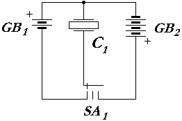
Here perhaps for visualization will opportunely to use the following electrotechnical analogy: we can consider the phenomenon of amplification of the sonoluminescence by means of focusing of energy of sound waves in the geometrical centres of symmetry of a cylindrical or spherical oscillators and receiving by means this of the reactions of nuclear synthesis, as a certain nonlinear nuclear amplifier. See the drawing 5, where the this phenomenon is conditionally designated by the operational amplifier. (For the greater visualization I on the operational amplifier depict the stylized atom.
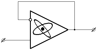
Drawing 5.
The period of the bipolar pulse causing one cycle of work of an oscillator (one act of collapse cavitational cavities in the centre of symmetry of a oscillator), is equal:
![]() 1 +
1 + ![]() 2 +
2 +
![]() 3, i.e. consists of three stages.
3, i.e. consists of three stages.
In the beginning of each period of fluctuations the forward front A - B of a bipolar pulse of electric current, which causes a abrupt radial distension of walls of oscillator during time ![]() 1 sufficient for that, in order to a running wave of lowered pressure
1 sufficient for that, in order to a running wave of lowered pressure
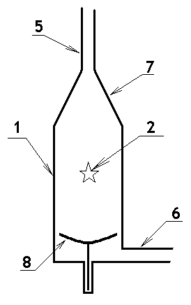
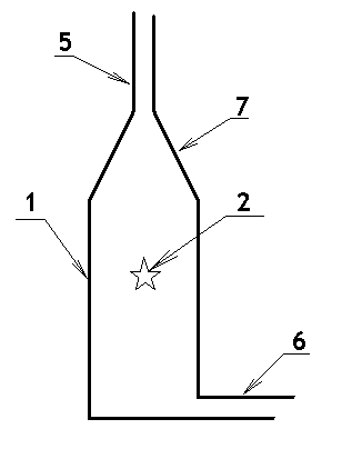
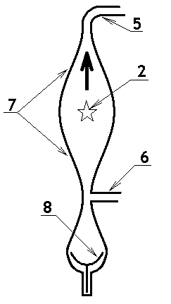
![]() [you can see the drawing 7] had time for spread with velocity v1, which close to usual velocity of a sound (for the given liquid) from walls to centre of symmetry of oscillator and to create there of cavitations of a bubbles, before to centre of symmetry will come later the travelling wave with increased pressure. (At the same time because of a radial distension there will happen the elastic deformation of walls of oscillator and in them will is stored energy.)
[you can see the drawing 7] had time for spread with velocity v1, which close to usual velocity of a sound (for the given liquid) from walls to centre of symmetry of oscillator and to create there of cavitations of a bubbles, before to centre of symmetry will come later the travelling wave with increased pressure. (At the same time because of a radial distension there will happen the elastic deformation of walls of oscillator and in them will is stored energy.)
Drawing 7.
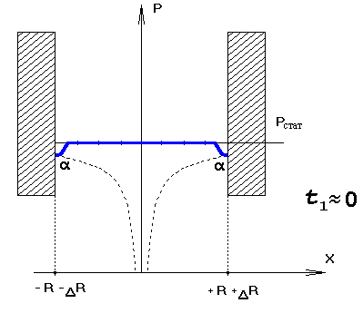
And necessary draw attention, that on the final stage, at the approach to the geometrical centre of symmetry of the oscillator, speed of distribution of a running wave of the high pressure can fundamentally exceed usual speed of distribution of a sound in the given liquid - the wave of the high pressure be re-born in the blast wave.
(The final instant of distribution of two travelling waves is shown on the drawing 9 - in centre of symmetry of oscillator exist cavitational a cavity, which be a surrounded the with different of a directions by the travelling wave of high pressure. And then the dynamic pressure of layers of a liquid, which surround of the cavitation cavity, thousandfold exceed average static pressure of a liquid, which is filling internal volume of oscillator. In these conditions and occurs collapse cavitations of cavities in centres of symmetry of oscillators.)
Drawing 9.
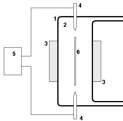
The first contour is filled with heavy water with the salts dissolved in her: 6Li and gases: heavy hydrogen and tritium. By numeral of 2 I designates a zone of sound irradiation of a liquid (zone where is passing of reactions of nuclear synthesis). Numeral 3 designates a tube, along which from sonoluminescence be outflow of hot water. Numeral 4 is designated of the heat exchanger. Numeral 5 - device for satiation of heavy water by gases tritium and heavy hydrogen. Numeral 6 is rotary pump, for pumping heavy water through sonoluminescence. The hot steam from by the heat exchanger 4 will rotate the turbine 7, which is conjugate with electric generator 8. By numeral 9 is designated else one the heat-exchanger, the heated up water from which follow by a tube 10 for household needs of the inhabitants, living by a beside electric station (for the district heating and the hot running water). By numerals 11 and 12 designate else two rotary pumps. Besides, as well as in case of with a traditional uranium reactor, around of a sound oscillator and the first contour we can install the radiation protection, which will make preventing of exit of radiation from the device. (On this figure she is not shown).
Very interesting idea was offered to M.A. Margulis - by the inventor: "The mode of getting of high-temperature plasma and realization of thermonuclear reactions" (already mentioned by me the patent 2096934 RU). However this invention in the engineering attitude was bad considered by his author, so in particular he offered in the description of own invention and in the formula of the invention a few difficultly, or is not clear how, for carry out technological processes. For example, he offers to use "the special metering device, which give of the gas vial" in a zone of sound fluctuations with density of power not less than 1014 watt . cm-3 - I doubt, that any device is capable to sustain long stay in a zone with such density of power, which typical for implementation of nuclear reactions. (The reader once again can look the drawing from specification of the patent of M.A. Margulis's.) Afterward mister M.A. Margulis's by some miracle offers to delete of the cavitation bubble from area with the specified power and to replace with his new portion of gases.
I even do not speak, what the author of the patent 2096934 RU has not described in the own work of the structure of the electric pulses, similar themes, which are submitted in this article on the drawing 6.
However in the invention as I already marked, mister Margulis M.A. has put forward rather perspective idea: amplification of process sonoluminescence, which realizations in the geometrical centres of symmetry of cylindrical or spherical oscillators with help of the constant electric field.
Now it is possible to consider his idea, but will necessary more correctly form her from the engineering point of view (see drawing 11).
Drawing 11.
However threat cavitational and electrochemical erosion of electrodes 4 all the same remain, what is lack of the device represented on a drawing 11, since reduces his reliability. It is possible to hope, what we will have a success, if in more simple the nonelectrode circuit, for getting reactions of controlled nuclear synthesis will use only of the one focussing of the sound running waves unload-compression.
(Also it is necessary to remind, what at 1950-55 years the large soviet physicist P.L. Kapitsa has created the microwaves generators of new type, which give power up to 300 kw in a continuous mode, and has found out, what in the high-frequency electric discharge in dense gases is formed the stable plasma cord, prospective temperature of the electrons in which 105-106 K. In due time this work (published in 1969 year) has opened a new direction of researches in the field of realization of controlled thermonuclear synthesis. In this connection it is possible to try to use in the device, submitted here by me, for increase of phenomena of thermonuclear reactions of the microwave the radiation, which we dispatch on the electrodes 4. However it is necessary to realize, what the process collapse of cavitational cavities it is quickly proceeding process, therefore make sense do sending of the microwave radiation on electrodes 4 only in the moment of a collapse of bubbles).
Anyway, the reasonings submitted here open a fine opportunity of getting of reactions of controlled nuclear synthesis. And, what very importantly, allow to make it ways, much more simple and incomparable cheaper, than at use the TOKAMAKs and other grandiose constructions.
Moreover, is quite possible, that the devices considered here appear rather compact, because of it they further can be used directly on autonomous vehicles, such diminutiveness probably never should be expected from other traditional projects of installations of nuclear synthesis.
Now we shall discuss some, only technical questions of manufacturing of sound oscillators and the electronic circuits inducing electric pulses of a necessary structure.
In the beginning we shall consider possible designs of oscillators.
Here we have such opportunities:
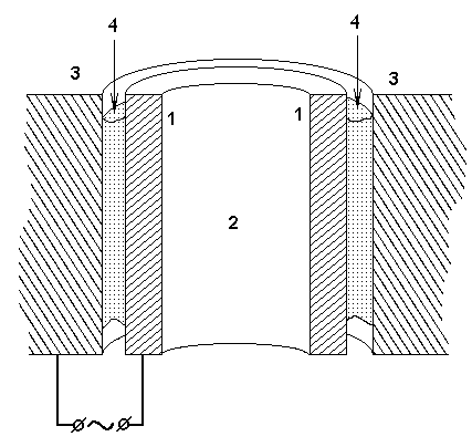
Firstly, use of piezoelectric materials. The oscillator essentially can represent the following device (see a drawing 13): the hollow cylinder, with rather thin metal walls 1 and the internal cavity, which in a consequence is filled by a liquid 2, where will make generating and collapse of the cavitational cavities. This cylinder 1 is used also as one of electrodes on which attach the electric voltage, forcing the oscillator to vibrate. The second electrode in a design of a oscillator is submitted by the external thick-walled metal cylinder 3. The gap between these metal cylinders is filled with substance 4, having piezoelectric properties.
Drawing 13.
We can make the spherical, as well as cylindrical, piezoelectric oscillators from the lead zirconate titanate,
PZT, - from the ceramics, for which during processing we can give any form. The technology of creation of a hollow spherical radiator is similar to creation of the fusform camera of the one-bubble cavitational reactor - see the text after a drawing # 40).
However, the substances, which have of the piezoelectric effect, be not enough stable to radiation and consequently not so well for use in a thermonuclear reactor. Besides, the phenomenon of the converse piezoelectric effect has small the coefficient of efficiency. Therefore below will be considered the opportunity of creation of spherical oscillators with electromagnetic focusing.
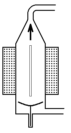
Other way of excitation of radial fluctuations of a cylindrical oscillator differs so, that instead of a variable electric field it is supposed to use a variable magnetic field. Similar oscillators already exist and are described in the literature. However it is possible to offer and other designs of the electromagnetic oscillatotrs, two of them are considered below.
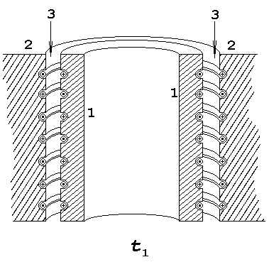
The basic design of such oscillator is shown on a drawing 15, where numbers 1 designate section of walls of a cylindrical oscillator (in this case he is made of a ferromagnetic alloy). The numbers 2 designate walls of the massive external cylinder (he also is made from ferromagnetic). Between an external surface of a cylindrical radiator and walls of an internal cavity of the big (covering) cylinder there is a gap 3, filled with gas.
Drawing 15.
The rings (the windings) of electric wires on cylindrical oscillator are connected consistently and get electric energy from one electrical direct-current source. On a drawing 17 schematically shown such consecutive connection of electric wires (by numeral 1 is designated cylindrical oscillator). The ring coils wires 2 are coiled in one direction, the ring coils wires 3 have other direction of coiled. That part of the ring the coils, which is closed cylindrical oscillator, on a drawing 17 be shown as the dotted line). Both ring coils of wires are connected consistently (direction of a electric current in wires, which is join of electric rings, be "from below is to upwards") however direction of electric current in rings 2 and 3 will be different, it on a drawing 17 reveal a symbols with "+" and " . " in circles, which I pictured near to specified electric rings.
Drawing 17.
The external massive cylinder of a oscillator too has a similar number of ledges with skirtings, only they are directed to inside, on meet to ledges of the internal cylinder. On these ledges also are coiled the coils of a wire. The general structure of a oscillator (a positional relationship of small and big cylinders) is shown in a transverse incision on a drawing 19.
Drawing 19.
Drawing 21.
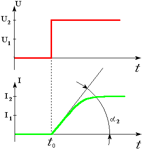
Us further will interest of the such characteristic of this signal of inclusion as a steepness of forward front "A" - "B".
We shall arrange, that such jerky signal of inclusion with a direction of an electric current how top-down, which flow in wires of the coil L, evoke in cylindrical oscillator by the own first front a radial distension of walls of a sound oscillator and as consequence in a liquid filling an internal volume of a oscillator, will start spread in the direction to the geometrical centre of symmetry cylindrical oscillator a traveling wave of the lowered pressure. Which later will created in the geometrical centre of symmetry of a oscillator necessary for us of the cavitation cavities.
After the expiration of the time τ1
quick moving of mobile contact of three-position switch SA1 in the extremely right-hand position will disconnect L from the source GB1, and will connect to coil
L of the source GB2, which already have the other polarity and the more high-voltage. Thus, the time diagram of electric currents now will so, how be shown on a drawing 23.
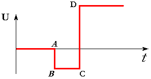
Drawing 23.
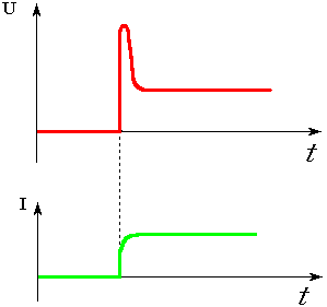
At inclusion of electrical key SA on a scheme, which parallel to the voltmeter, and consist from of the ammeter and a strangler will be sent of the signal of inclusion (the voltmeter will show abrupt the jump of the electrical voltage). However caused of by this the by jump of voltage, of the electric current, which be flowing through the ammeter and a strangler, will have substantially smaller velocity of increase of a implication, i.e. the steepness of forward front of an electric current will be much less implication of steepness of forward front of a signal of inclusion of a voltage (see drawing 25).
Drawing 25.
Drawing 27.
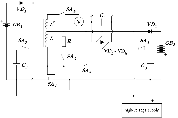
The electronic scheme submitted on a drawing 28 works so: in the beginning the electric current through the coil L does not pass, since mobile contact of three-position switch SA1 is in the average position so, that the electric circuit is broken off. At this time the high-voltage condenser of small electro-capacity C3 will be charged from a high-voltage source. Later, when shall made action of the switch SA3 then the source of high-voltage switch-off from a capacitor, and the capacitor C3 will connected to a scheme. The high-voltage diode VD2 has such polarity of connection with scheme, what he be closed by the high voltage of condenser C3, and he (the diode) not give to him opportunities be unloaded through rather low-voltage galvanic cell: GB2.
Now, if to move the mobile contact of three-position switch SA1 in the extremely right-hand position then we will link up the circuit and in the coil L will is flowing an electric current. On a drawing 29 are shown the time diagrams of the voltage enclosed by the ends of the coil, and an electric current proceeding in her.
Drawing 29.
Later of the micro explosion, the mobile contact, already before to us met in other electric schemes, of three-position switch SA1, should be established in middle position. Thus all electric circuits intended for excitation of fluctuations of walls cylindrical oscillator be are disconnected from coil of exciting L. (Work of these electric circuits of excitation of fluctuations was considered by us earlier, therefore on a drawing 30 I shall not show these sites of a scheme).
Later we do simultaneous switching of mobile contacts in switches SA4 and SA5.
The electric voltage, generated in coil L by fluctuatings of the walls cylindrical oscillator, through closed contact of switch SA4 proceed on a straightening to the diode rectifier VD3 - VD6 and further on condenser C4, and from his cleats the consumer can receive a constant electric voltage. I.e. we managed to decide of the considered task - we receive a source of a electric current, the suitable for needs of the consumers.
Now it is necessary to explain assignment of other elements represented on a drawing 30: of the voltmeter, of the additional coil of inductance L', the resistance R,
the switches
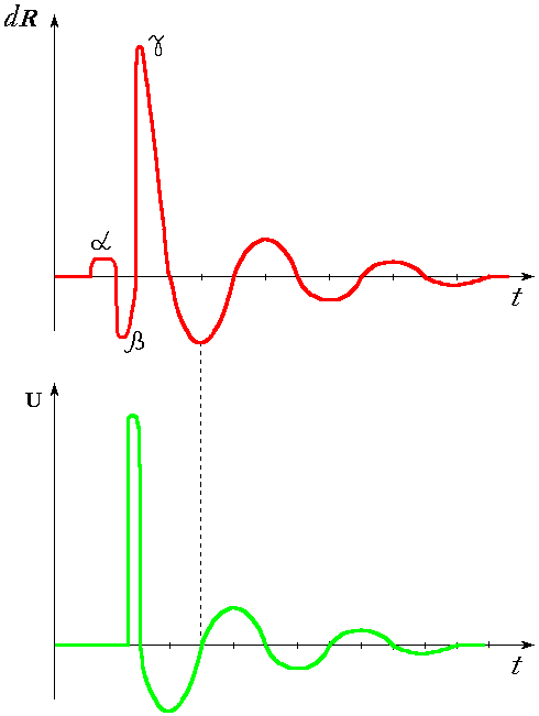
SA5 and SA6. For this purpose we in more detail shall consider mechanical fluctuations of walls of oscillator, which is generating electric energy. (After each separate act of collapse cavitational cavities from the geometrical centre of symmetry starts to be diffused the running shock wave, which, having reached walls of oscillator, be reason of their fading mechanical fluctuations (see the upper diagram on a drawing 31). Where on an axis of abscissae is time t, on an axis of ordinates is postponed of the change of radius of the oscillator: dR.
Drawing 31.
On a drawing 32 is submitted the local transverse incision of the piezoelectric filling, existing between walls of oscillator and an external massive metal environment covering him (the surface of section passed through the geometrical centre of symmetry of oscillator). The number 1 designates a metal wall of a oscillator, by number 3 - a metal wall of the external massive environment covering a sound oscillator. Numeral 2 designate two layers of the substance having piezoelectric effect. The new element entered by me in discussion is the thin metal layer which is situated in thickness of a piezoelectric material parallel to a surface of oscillator. (In other words, this thin metal layer is parallel to walls of oscillator and parallel to inside walls of an external massive metal detail, which covering sound oscillator.) As a matter of fact we now have received two piezoelectric cells - the thin metal layer 4 carries out a role of the metal capacitor plates, applied to a surface of two condensers consistently included in an electric scheme, and in them in quality dielectrics is used the substance, which have characteristics of the piezoelectric effect. (See a drawing 33, on he for a designation of the appropriate elements are used the same numerals, as and on a drawing 32). Thus, we in the right to replace one condenser C1 to two: C1' and C1' '.
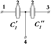
Drawing 33.
The drawing 34 by the own set of compound electronic elements and by their functional assignment very strongly reminds of the scheme, shown on a drawing 30, difference consists only in replacement of coils of inductance by piezoelements. The consistency of operations of switches the same as on the electric scheme, submitted by a drawing 30. (After was act of collapse cavitational cavities, mobile contact of three-position switch SA1 will is established in average position, what do disconnecting of piezoelements from of a schemes of excitation. Next simultaneously mobile contacts of switches SA4 and SA5 is switch on, it allows to generate of the electric power and connects to scheme a threshold element (the voltmeter). Next mobile contact SA4 is switch off, and after a small time interval mobile contact SA6 is switch on, etc.)
Now I show the general electric scheme, at which is uniting and the electrical schemes of the generating of the electric power and a schemes of excitation, you may look a drawing 35.
Drawing 35.
Now it is necessary to execute the promise: to present electronic schemes of switches on a basis of the bistable electronic elements. I shall show work of these switches with use of transistor schemes. Switches SA1, SA2, SA3 can be made under the scheme, which be submitted on a drawing 37.
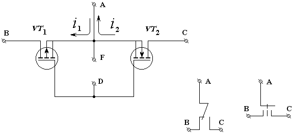
Drawing 37.
Feature of work of this electronic switch submitted on a drawing 38, be in that, what he should commute of an alternating electric current. (At this switch The variable voltage shall be linked on the clamps: "A" and "B";). The electric voltage on clamps "D" and "F" administer by the electric switch. If on clamp "D" give positive potential concerning clamp "F", then both transistors will open and through the switch will be flowed the alternating electric current (during one half-period the electric current will flow through one transistor, during the second half-period through other transistor, it is caused by use in an electronic scheme of diodes). If on clamps not send managing voltage, then both transistors are closed and the switch does not miss through itself an alternating electric current. For comparison near to the electronic scheme of the switch is submitted her mechanical analogue.
It, perhaps, everything, what I wanted to tell about principles of functioning of oscillators and the appropriate electronic schemes. Here still need further consideration a lot of the important questions, but I already no want discussing theirs. The electronic schemes, submitted here have schematic character, they be given here only for demonstration of assignment and a sequence of operation of those or another electronic elements. In real device of the oscillators the electronic schemes can have serious differences. So, for example, on the electronic schemes shown on drawing 20, 21, 35 and 36 there are galvanic cells of a direct current: GB1 and GB2. Therefore can arise the erroneous opinion, that for own the of work the oscillators the all time use energy of this galvanic cells. In reality, the galvanic cells will be used only on the initial stage - for start of work of oscillators, and in a consequence galvanic cells should be detached from the schemes of excitation, and all electric power necessary for work of a oscillator will be generated by the oneself oscillator. (In this case galvanic cells act in a role of a similar role of the electrical accumulator battery, which we used for launching, in the automobile, supplied with the engine of internal combustion).
Necessary to notice, that, considering submitted here of the way of the production of the electric power by the fluctuating walls of oscillator, I at all do not offer completely to refuse production of the electric power with the help of the external generator, with the rotor, which rotates from the steam turbine. On the contrary, I mean compatible production of the electric power how from the external generator, reducible in movement by the steam turbine, so, and by the getting of the electric power from fluctuations of walls of oscillator. It is necessary to take into account, what the coefficient of efficiency of the steam turbine approximately 45 %, coefficient of efficiency of the electric generator, with rotor, which rotate from the steam turbine, approximately 90 %. Thus, coefficient of efficiency of transformation of the thermal energy of the hot steam in the electric power at use only the external generator, which to set in motion by the steam turbine, will is approximately 40 %. While process of generating of the electric power by directly mechanical fluctuations of walls of oscillator at once will give coefficient of efficiency approximately 80 - 90 %. It is necessary to remember and this, that the electric power a more qualitative kind of energy in comparison with thermal energy (more qualitative in the those sense, what is easier for transferring the electric power at a great distances and she is easier for of converting to other kinds of energy - in energy of movement or in the same of thermal energy. While to impart on a great distance and, what the most important, to transform thermal energy in other kinds of energy frequently more inconveniently).
But, moreover, due to extraction of energy from of the fluctuations of walls of a oscillator will arise the effect of the electromagnetic damping, which will did accelerating of the process of the dying-out of mechanical fluctuations of walls of a oscillator, what will allow a thicket to make acts of birth and of collapse of cavitational cavities in the geometrical centre of symmetry of a oscillator, i.e. then be opportunity appreciably will increase the general capacity of the device.
In February 2006 in magazine "The technology for youth" was published my article "Working pulse of a man-made star".

In October, 2006 in the same magazine was published the critical article of the V.A. Zolotuhin's

The design of reactor, which was proposed by Zolotuhin, certainly, is very interesting. However he is not deprived of the certain lacks.
So, the channel for removal of vapor gases of the microexplosion in oscillator of V.A. Zolotuhin's is located not by the very rational mode. The area of section of channel, certainly, will little, but he approaches to the working chamber of oscillator on the part of focusing lenses - in those places which the most active participation in focussing, and its the channel do, let and little, but a disharmony in focussing waves. At the same time the rim discoid chambers of a reactor has rather big section and directly is not used for focussing waves, but only as channel of the mhd-generator.
In this connection it would be logical to connect these tubes to a rim of a disk. For example, so:
Drawing 39.
Where by numbers are designated: 1 - the working chamber of a reactor; 2 - the channel of removal of the vapor gases of the microexplosion; 3 - the generator of a shock wave; 4 - an acoustic lens of the big speed of a sound; 5 - an acoustic lens of small speed of a sound; 6 - the ring channel disk of the Holl MHD-generator; 7 - a load-bearing unit - buffer; 8 - electromagnetic wires; 9 - the generator of ultrasonic waves.
Thus the working chamber of a reactor has the form of a spindle.
In such design already there is no rim (the ring channel disk of the Hall MHG-generator), which does not accept participation
in creation of the spherical waves. Only two small local areas, located along an axis of a reactor, are not used in focussing.
Through them to the working chamber of a reactor and connect tubes, where is flowed the working liquid, with dissolved in her
D, T, Li, U, Pl... Certainly, will make the working chamber of such reactor much more difficultly: for it necessary to take
of the fusiform billet out of the metal, which is refractory to the heat, but, at the same time, this the metal must be easily
accessible to chemical milling. We establish this the fusiform billet in the specially casting form, which have inner geometry
similar to external geometry of a lens of the increased speed of a sound, and fill up her with metal, from which we will make
the lens of the increased speed of a sound. Then after congelation of the metal we formed by means of a lathe and a grinding
machine of the external form of a lens. Operational development of an external surface of a lens of the increased speed we do
with help of laws of refraction Snellius. Later we drill along axis of the fusiform billet of the through channel and flush a
chemical solution, which is carrying out chemical milling of metal, from which is made of the billet - so we can get of the
necessary fusiform a cavity.
All it, certainly, more difficultly, but the similar design of the mono-bubble reactor, in
which there is a focussing of cylindrical waves in spherical, will allow, how say, "to lick" of the geometry
of the working chamber. Similar the mono-bubble reactor will have characteristics better, than described by V.A. Zolotuhin.
The existing level of technics in the given area is presented by patents ##
2096934 RU, 2125303 RU, 2258268 RU, 2005/0129161 US.
Reasoning from the analysis of the designs, declared by their authors, it is possible
to draw a conclusion, that they will organize mandatory circulation of a liquid
in the first contour of a reactor by means of the special external pump - in
one case it is underlined obviously, in others about it is possible to judge
with help of the indirect attributes.
It is necessary to notice, however, that in shown here the cavitational reactors of nuclear
synthesis we probably can use a part of energy of microexplosions for organization of
pumping of the liquid through the working chamber of a reactor. (The phenomenon of movement of a liquid at the action of
sound waves was described in the literature is, you can see for example, in Big the Soviet
Encyclopedia "the acoustic wind".)
It allows to refuse use of the external special pump, which do pumping of a liquid in the first contour of a
reactor, or we can reduce its capacity.
For this purpose it is necessary to use in a designs of a reactors additional elements, which permit
move of the half waves of the high pressure of sound waves in one direction and
to suppress their distribution in other direction. As similar elements we can use
the valves, the cumulative funnels, the reflectors, etc.
The general principle of work of such "sound" pump I show on a figure 42.
Drawing 42.
The numerals 3 and 4 designate the valves, which to leak a liquid only in one direction. In the chamber 1 after of microexplosion
2 will the surplus pressure of a liquid, as a result the valve 3 opens and the portion of a liquid retire
through valve the explosive chamber 1. After that the valve 3 will close. The working liquid in
the chamber 1 cools down, i.e. reduces the own volume, and in the chamber the
low pressure will created, therefore the valve
4 opens and the new portion of a liquid flows into the chamber 1 through him. Whereupon the work cycle will repeat.
However use of valves can appear not effective because their opening and closing and the cooling of a
liquid demands time.
Therefore in case of with the cavitational nuclear reactor for
creating the circulation of a working liquid in the first contour, it will
be better to use not valves, but the reflectors and the collecting funnels, which change direction
of motion of shock waves of the high pressure caused by microexplosion, how it I showed on a figure 43.
Drawing 43.
Where numeral 1 designates the explosive chamber filled by a liquid. By numeral 2 I label the nuclear
microexplosion, caused by collapse cavitational of a cavity. The numerals 5 and 6 designate pipes, in
which the liquid flows. We owes make
the dispositions of the funnel 7 in relation to nuclear microexplosion so, that the
shock wave of the high pressure enters into a wide part of funnel, later the wave will concentrate
at its narrow end and leaves the working chamber, going in a pipe 5 of the first contour.
The reflector 8 on the contrary, returns a shock wave of microexplosion in the working chamber,
reducing an opportunity of its penetration into a pipe 6 of contours. Thus, under influence of
shock waves of nuclear microexplosions the liquid in the first contour of the cavitational
thermonuclear reactor gets the directed movement.
The reflector 8 can generate also the electric power from a shock wave of nuclear microexplosion
due to the reverse magnetostriction effect or the phenomenon of an
electromagnetic induction.
Probably also creation of the sound pump only with one tunnel without a special
reflector how you can see on a figure 44.
Drawing 44.
In this sound pump the geometry of the explosive chamber also will so, that
conditions of penetration of shock waves of the high pressure, resulting as
result of the microexplosions, for tubes 5 and 6
will various. Similar sound pumps can be
applied and in earlier described the cavitational nuclear reactors.
In this case tubes of the first
contour connect to the working chamber of reactors how is shown on figures 45, 46, 47 (arrows note a direction of movement of a liquid, under action
of shock waves of nuclear microexplosions).
Drawing 45.
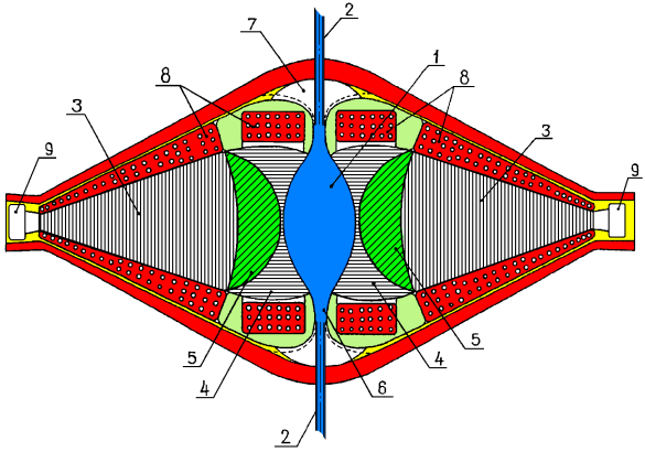
On a figure # 45 I show the connection of the tubes of the first contour with the cavitational thermonuclear reactor with a cylindrical oscillator.
Drawing 46.
On a figure # 46 I show the connection of the tubes of the first contour with the cavitational thermonuclear reactor, filled by a dielectric liquid.
Drawing 47.
On a figure # 47 I show the
structure of the first contour of the monobubble cavitational thermonuclear reactor with
cylindrical concentrating lenses.
Work of the sound pump of this reactor should be considered more in detail.
The spindle-shaped chamber of such reactor
is represented as a matter of fact as two flared funnels 7, which turned face-to-face by flared parts.
On a narrow extremity of one of funnel it is necessary to establish the device, which make return of the sound waves back in the
chamber, for this purpose we can use the reflector 8. The tube, by means which we inject a liquid in the reactor 6, is connected perpendicularly to
axis of the spindle-shaped cavities in the narrowest part of funnel. In this place of the funnel
after of the nuclear microexplosion 2 will be the
greatest speed of current of a liquid and consequently, according to
equations of Bernoulli's, the least
pressure, what will cause inflow of the liquid from the injection tube in
the working chamber of a reactor.
The note:
I have not found in the Russian-speaking technical literature of the description of pumps of a similar construction and have made the application on the invention in Rospatent. However the search which has been carried out by experts of Rospatent, has allowed to find out almost full analogue -
the patent for invention # 3270688 US. Nevertheless, I have decided to leave the description of work of the sound pump on this site to show more evidently its application in the functioning a thermonuclear reactor.
In conclusion, I do cautious assumptions concerning where can find using of oscillators. I suppose, that they have the big prospects both in peaceful and in military spheres:
1. Stationary sources of thermal and electric energy (it is possible, on the basis of the principles, submitted here, it will be possible to construct stationary power stations, like already existing atomic power stations. It will allow to solve a problem of an exhaustion of hydrocarbonic fuel and so-called the "greenhouse effect", already arising in foreseeable the future before mankind).
2. It is possible, that devices considered (examined) here, will of enough by compact, for using them as energy sources in various vehicles. In particular as steam boilers for steam engines. Similar devices can find using on nuclear submarines, the nuclear ships, nuclear planes, nuclear helicopters, nuclear trains, nuclear automobiles and even how sources of energy for the anthropomorphic (humaniform) robots. It here now it will be quite pertinent to remind, that modern constructions of steam engines have quite good efficiency, are compact enough, reliable and silent in work (see literary sources 10 and 11). Perhaps the one lack of steam engines it is the steam boiler and necessity in a heater of a liquid. One can hope, that using of cylindrical oscillator or spherical oscillator will remove these problems and will make steam engines more competitive in comparison with engines of internal combustion.